Thermal Design And Simulation of Machine
Including natural cooling design, forced air cooling design, liquid cooling design.
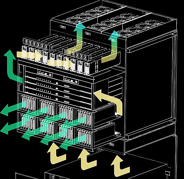
Natural heat dissipation with high power consumption is a challenge of thermal design. OREA has completed four industrial switch cases through thermal simulation analysis. System engineers attach positive and negative sub-cards to the upper and lower surfaces of the shell, respectively, and diffuse internal heat to the surface of the shell by means of heat conduction.
Typical 9U board, transverse heat dissipation channel with left in and right out. To provide maximum heat dissipation, 120 x 120 and 92 x 92 fans are staggered to ensure full coverage of all slots. This heat dissipation method is reliable and stable, and is mostly used in communication equipment. More than 30 cases of related design have been completed by OREA.
When the rising curve of power consumption of electronic products and the declining curve of energy saving and emission reduction trend increasingly tend to intersect, the liquid cooling technology is timely born. Liquid cooling efficiency is high, up to 20 times more than the traditional air cooling mode, can solve the heat dissipation problem of higher heat consumption; In the high heat consumption, mass layout of IDC room and other industries will play an important role. OREA has also carried out research on the combination of liquid cooling technology and structural design, and will provide customers with liquid cooling cooling solutions.
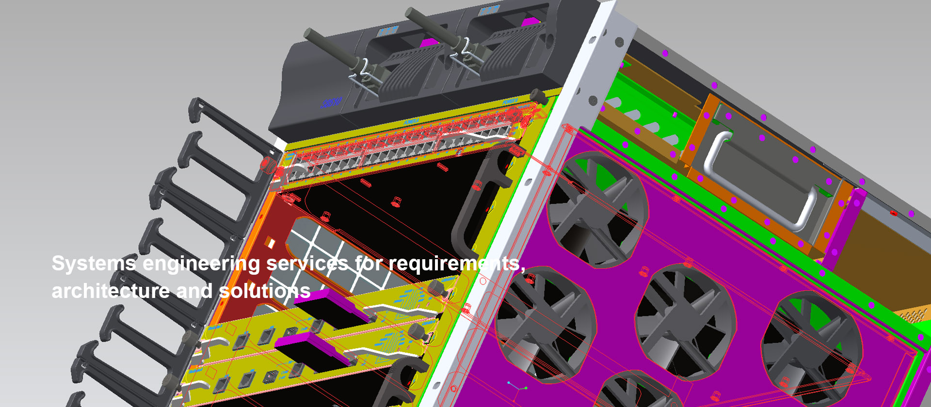
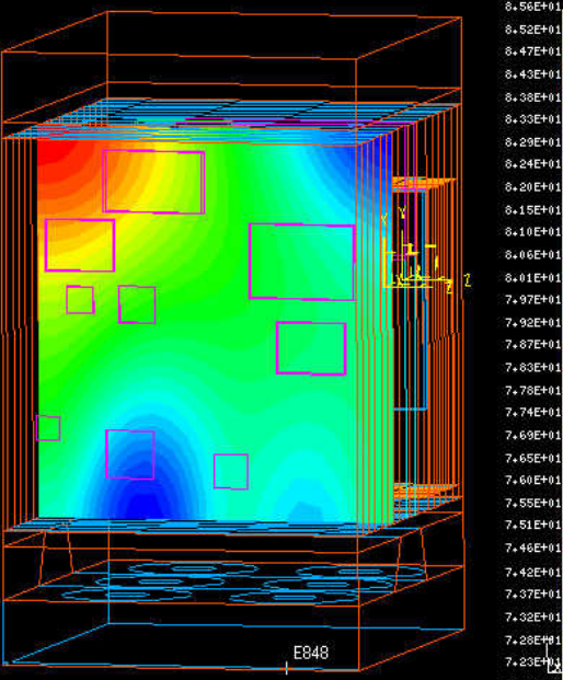
System Level Thermal Design And Thermal Simulation
Design air duct, fan, veneer, radiator and so on, and carry out thermal simulation of the whole machine.
In the given heat dissipation environment, firstly evaluate the feasibility of the whole machine heat dissipation, and preliminarily complete the air duct design and fan selection; Carry on the detailed thermal design of the veneer, complete the radiator design; Finally, the thermal simulation of the whole machine is carried out again to optimize the design of the air duct and fan selection in the early stage.
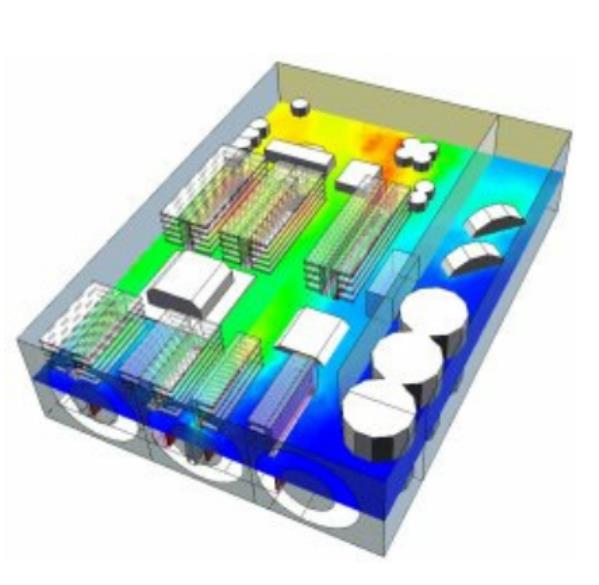
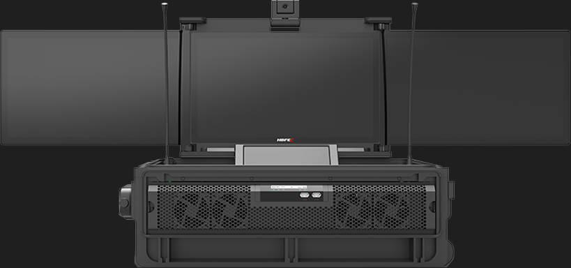
The temperature nephogram of the whole system and the velocity vector diagram of the large host system can simulate the integration relationship of all elements of the system, and can simulate the changes of the wind channel and wind speed under different system layouts, so as to optimize the most suitable system heat dissipation scheme. Currently, OREA Engineering has completed several thermal design projects for large mainframe systems.
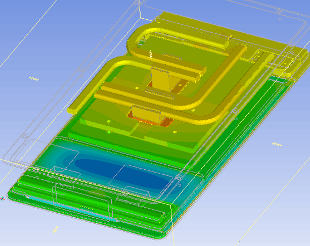
Module Thermal Design And Simulation
In a given heat dissipation environment, adjust the internal layout of modules to eliminate local hot spots.
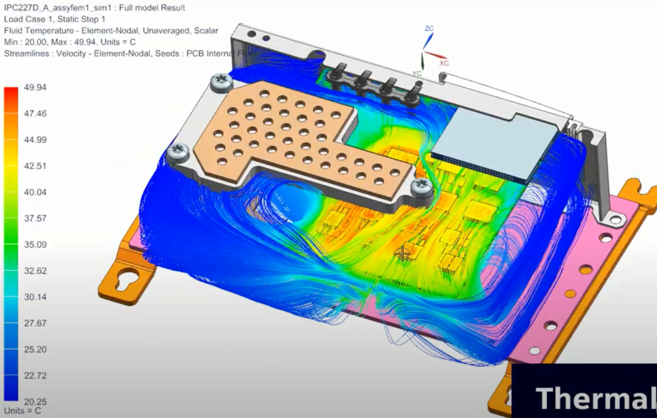
In a given heat dissipation environment, adjust the internal layout of modules to eliminate local hot spots. Temperature cloud diagram of the switch module and monitoring module and velocity vector diagram of the switch module and monitoring module.
In addition to the power consumption of the chip itself, the influence of the system environment on the air volume and wind speed should also be considered for module heat dissipation. The radiator should be designed in accordance with the wind direction of the system duct. Heat sinks can use heat pipe, profile, VC and other different processes, need to be customized in the limited structural space, has reached the maximum heat dissipation effect.
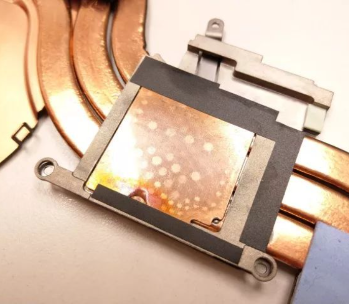
Device Thermal Design And Simulation
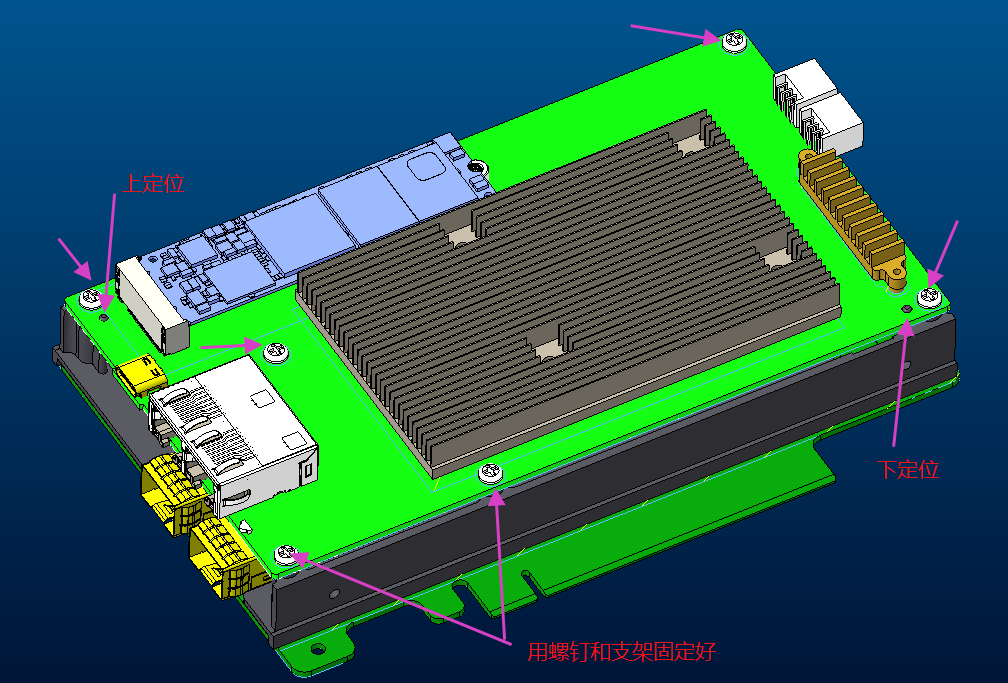
Improving measures such as strengthening heat dissipation capacity, optimizing heat dissipation components and adjusting heat dissipation resources are taken for key components.
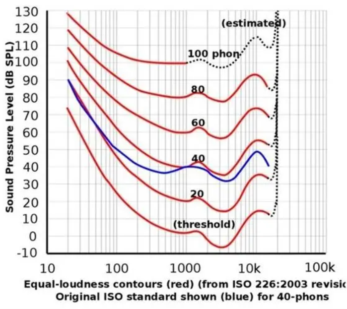
The noise of the system should be considered in the thermal design of the system. We consider both thermal design and noise control. Through reasonable air duct design and optimization, reasonable fan selection, the noise of the whole system is controlled within the required range. In the complex system noise design, the system noise is 70.8~73.8dB-A when the high temperature fan is at full speed. The system noise is 60~63dB-A when the speed is regulated at room temperature (60% of the full speed).
The picture shows the fan selection table:
Hardware Design
OREA can provide customers with non-core hardware design services, including hardware stacking, requirements management, PCB schematics, LAYOUT, etc. Integrated development of structure and hardware under one management environment will greatly improve the development efficiency...
Electromagnetic Shielding
Electromagnetic shielding (EMC/EMI) design solutions are widely used in the medical, defense, and communications industries to provide comprehensive protection for equipment from the external environment and any potential interference that may affect its performance...
FULL SUPPLY CHAIN
SOLUTION from
DESIGN to PRODUCTION
CONTACT US
+86 18600523371